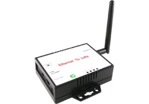
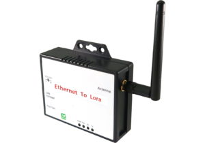
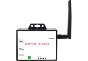
LR200EM
Ethernet
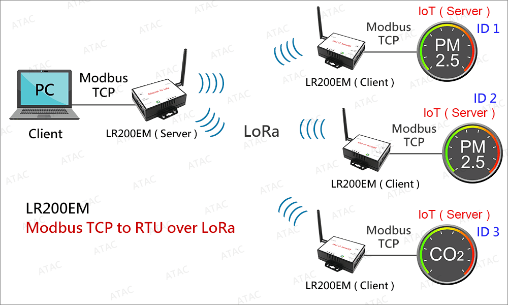
Die drahtlose Datenübertragung über LoRa kann in einer Vielzahl von Anwendungen verwendet werden, wie z. B. Modbus TCP zu Modbus RTU, Modbus TCP zu Modbus TCP, Modbus RTU zu Modbus RTU, Ethernet zu Ethernet Pass-Through, Seriell zu Seriell Pass-Through, Modbus Digital Eingang/Ausgang und Modbus-Analogeingang/-ausgang.
Lesen Sie Daten von Modbus-Geräten, RS485-Geräten, TCP/IP-Geräten, digitalen Eingängen und analogen Eingängen drahtlos über große Entfernungen über LoRa.
Senden Sie Daten/Befehle drahtlos über große Entfernungen über LoRa an Modbus-Geräte, RS485-Geräte, TCP/IP-Geräte, digitale Ausgänge und analoge Ausgänge.
LoRa is an ideal wireless solution for transmitting data of which the data packet is less than 150 bytes (the less the better) up to 800 meters in a free open area. The transmission distance can be further with the use of outdoor high gain antennas.
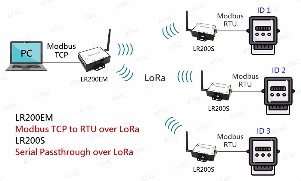
LR200 converters with the same frequency and encryption key will be grouped into the same LoRa network when they are powered on. Unlike transmission over Ethernet which is full duplex, devices connected to the same LoRa network work exactly like connecting to half duplex RS485 but over wireless (LoRa). In the same LoRa network, only one master can broadcasts (sends query) to all other slaves (devices). When the master sends out a query, all other slaves (devices) will receive this query, only the device with the corresponding ID will reply, all other devices not with the corresponding ID will ignore this query.
Limitation of LoRa
Data loss will occur with transmission over LoRa. This is because each data packet will be sent ONLY ONCE which means a certain data packet will be lost if it fails to be received by the other end.
Data transmission speed over LoRa is only 100 bytes ~ 120 bytes per second.
For Ethernet-to-Ethernet passthrough over LoRa (LR200E to LR200E), and Serial-to-Serial passthrough over LoRa (LR200S to LR200S), only one end can send data to the other end at the same time. Data will get messy if both ends send data to the other end at the same time.
LoRaWAN and the 3rd party LoRa devices are not supported by LR200 LoRa converters.
How much data loss will occur transmitting over LoRa ?
Actual field testing is the only way to find out how much data loss will occur. Because it depends on data packet size, distance, and interference, unexpected factor,.. etc.
How to reduce data loss ? How to increase transmission distance ?
Data packet less than 150 Bytes or the less the better
Distance less than 800 meters (2600 ft) or the shorter the better
Mount the antennas at a higher position. As less as possible of obstructions and interference factors in the straight path between the antennas at both ends. The obstructions and interference factors are such as walls, electrical noise, etc.
Use a high gain omni antenna on one end, and a high gain directional panel antenna on the other end. Make sure the directional panel antenna is pointing precisely to the other end’s antenna.
Can LoRa transmission pass through the concrete floors and walls ?
LR200 LoRa converters testing result shows it is able to pass through 10 concrete 30-cm thick floors. However actual testing in the actual operating environment is required to find out the actual performance.
Wenn ein mit LR200 verbundenes Gerät sendet und alle anderen mit LR200 verbundenen Geräte im selben LoRa-Netzwerk diese Übertragung empfangen, führt das dann zu Verwirrung?
Die Anwendung des Benutzers muss anhand der ID-Nummer erkennen können, welches Gerät angerufen wird. Ebenso wie bei der Modbus-Anwendung muss jedes Gerät eine ID-Nummer haben, sodass nur das Gerät mit der richtigen ID-Nummer antwortet.
How many units of LR200S can work with one LR200E / LR200EM in the same LoRa network ?
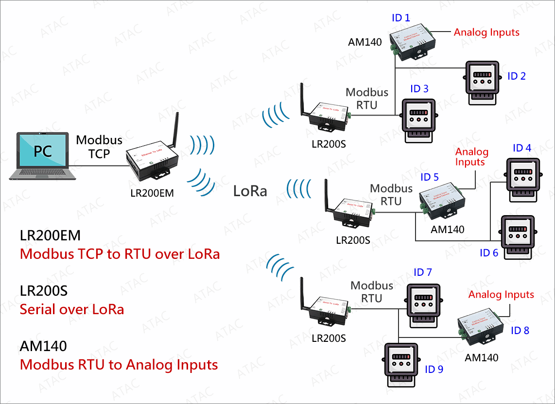
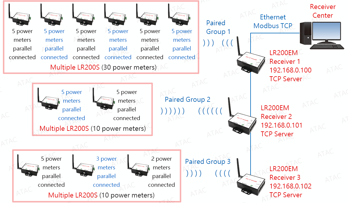
RS485 over LoRa operates like a half duplex RS485. One response for one quiry. A maximum of 6 to 10 units of LR200S is recommended to operate with one LR200E / LR200EM in the same LoRa network.
How many Modbus RTU devices can be parallel connected to one LR200S ?
A maximum of 6 to 10 Modbus RTU devices are recommended to be parallel connected to one LR200S.
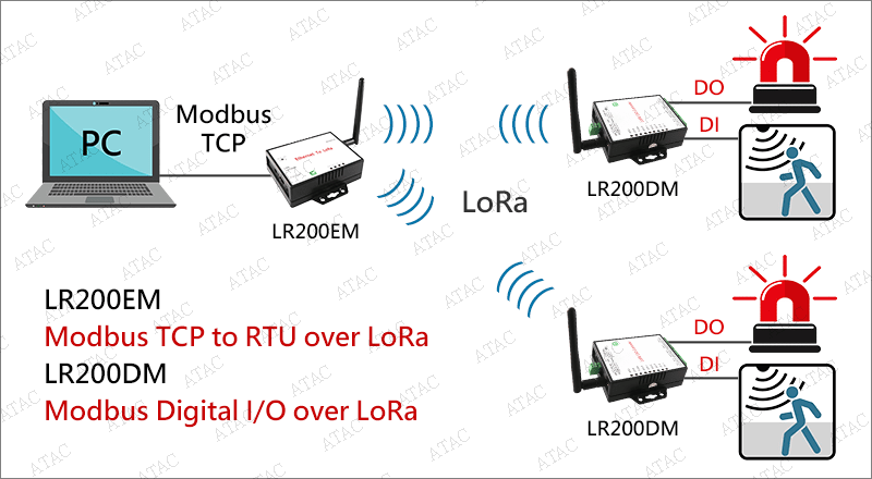
Erhalten Sie den digitalen Modbus-Status und senden Sie mit Modbus-TCP-Befehlen drahtlos digitale Modbus-Triggersignale über LoRa

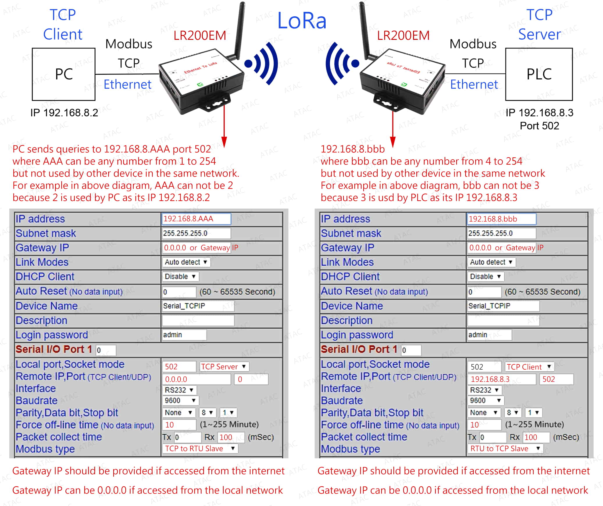
Modbus TCP zu Modbus RTU drahtlos über LoRa

Modbus TCP digitaler Ein-/Ausgang drahtlos über LoRa
Modbus TCP analoger Ein-/Ausgang drahtlos über LoRa
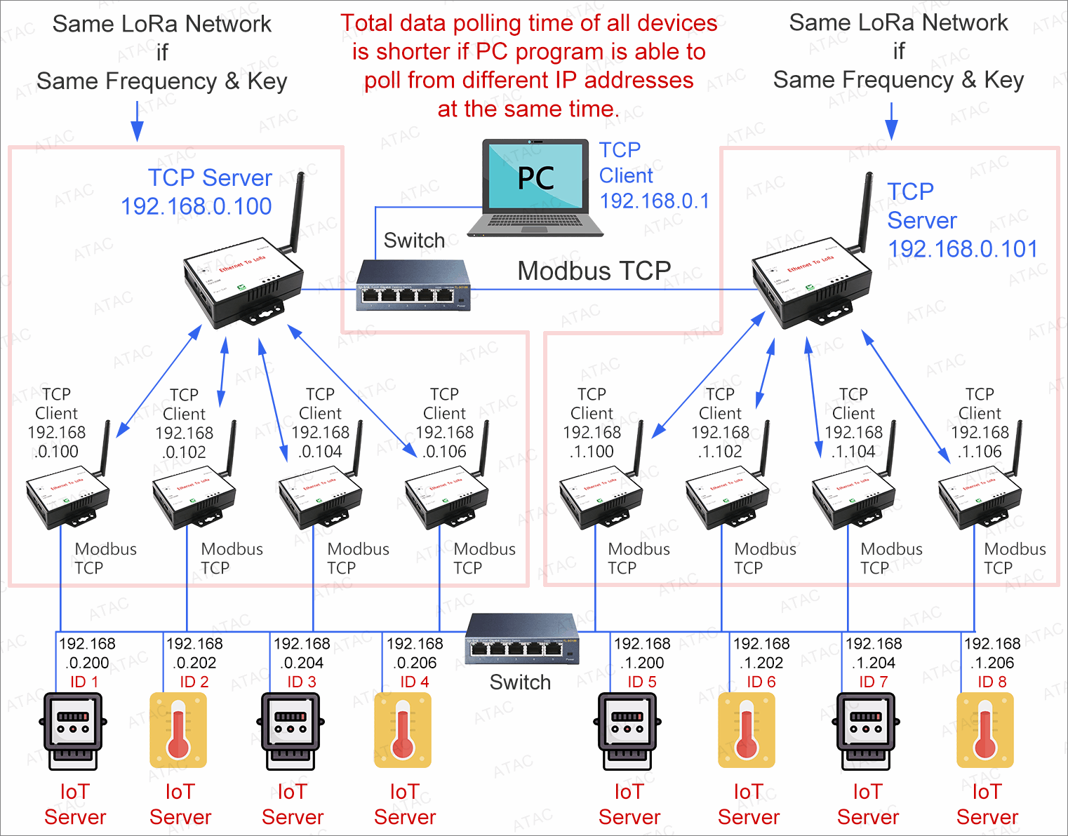
Modbus TCP to Modbus TCP wirelessly via LoRa
LoRa-Netzwerk-Setup
Jeder LR200 LoRa-Konverter besteht aus einer Hauptplatine und einer LoRa-Platine
| Model | Beschreibung | Main board | LoRa board |
| LR200EM | Modbus TCP zu RTU über LoRa | Ethernet to UART | UART to LoRa |
| LR200E | Ethernet zu LoRa | Ethernet to UART | UART to LoRa |
| LR200S | Seriell zu LoRa | RS232/485/422 to UART | UART to LoRa |
| LR200U | Serial (USB VCOM) to LoRa | USB to UART | UART to LoRa |
| LR200DM | Modbus RTU DIO over LoRa | Digitale I/O | UART (RTU) to LoRa |
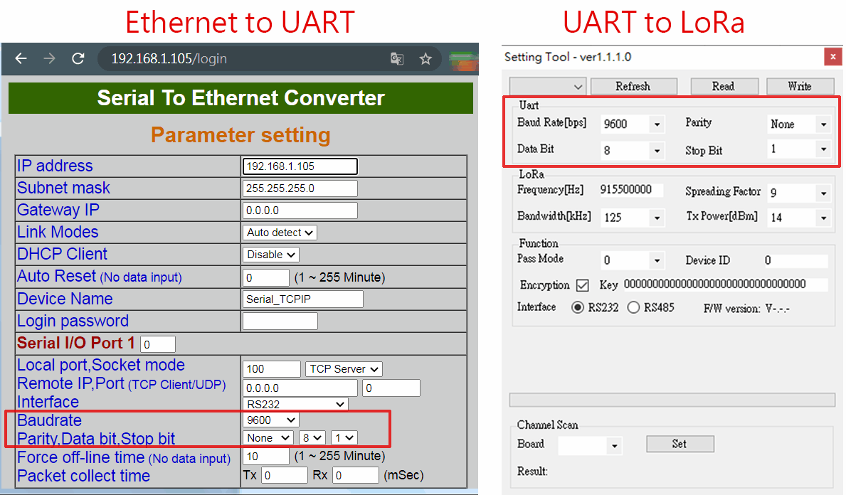
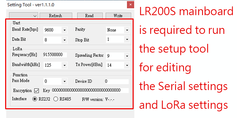
Sowohl die LoRa-Karte als auch die Ethernet-Karte enthalten serielle Parametereinstellungen wie 9600/N/8/1. Diese seriellen Parametereinstellungen beider Karten müssen gleich sein, damit beide Karten miteinander kommunizieren können.
Das LoRa-Board muss auf dem LR200S-Mainboard installiert und über RS232 oder RS485 mit dem Computer verbunden werden. Führen Sie dann das LoRa-Setup-Programm aus, um das LoRa-Board einzurichten. Einzelheiten zum LoRa-Board-Setup finden Sie im Dokument.
Melden Sie sich über die Browser-Webseite beim LoRa-Konverter an, um die Ethernet-Karte zu konfigurieren.
LoRa-Netzwerkgruppierung
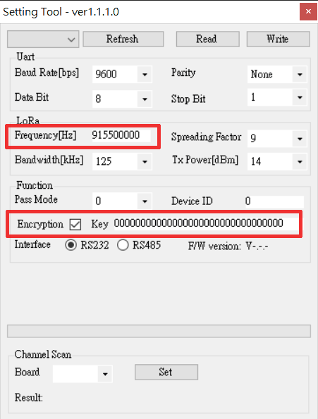
LR200-LoRa-Konverter mit derselben Frequenz und demselben Verschlüsselungsschlüssel werden beim Einschalten als dasselbe LoRa-Netzwerk gruppiert.
LoRa funktioniert wie eine drahtlose Halbduplex-RS485. Nur ein Master kann an andere Slaves im selben LoRa-Netzwerk senden, und der Slave mit der entsprechenden ID antwortet auf die Übertragung.
Die Frequenz zwischen zwei verschiedenen LoRa-Netzwerken muss sich um mindestens 0,5 MHz unterscheiden, um gegenseitige Störungen zu vermeiden. Angenommen, es gibt drei verschiedene LoRa-Netzwerke. Die Frequenz jedes LoRa-Netzwerks kann beispielsweise 915,5 MHz, 916 MHz und 916,5 MHz betragen.
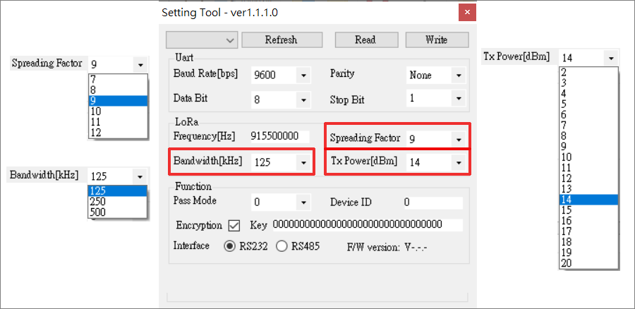
Konfiguration der LoRa-Datenrate
Drei Parameter können angepasst werden: TX-Leistung, Bandbreite und Spreading-Faktor. Wenn Sie die Sendeleistung verringern, sparen Sie zwar Batterie, aber die Reichweite des Signals ist natürlich geringer. Die beiden anderen Parameter ergeben zusammen die Datenrate. Dies bestimmt, wie schnell Bytes übertragen werden. Wenn Sie die Datenrate erhöhen (die Bandbreite vergrößern oder den Spreizfaktor verringern), können Sie diese Bytes in kürzerer Zeit übertragen. Für diese sieht die Berechnung ungefähr wie folgt aus: Wenn Sie die Bandbreite verdoppeln (von BW125 auf BW250), können Sie doppelt so viele Bytes gleichzeitig senden. Wenn Sie den Spreading-Faktor um eine Stufe verringern (von SF10 auf SF9), können Sie doppelt so viele Bytes gleichzeitig senden. Durch die Verringerung des Spreading-Faktors wird es für das Gateway schwieriger, eine Übertragung zu empfangen, da es empfindlicher auf Rauschen reagiert. Man kann dies mit zwei Personen vergleichen, die sich an einem lauten Ort (z. B. einer Bar) aufhalten. Wenn Sie weit voneinander entfernt sind, müssen Sie langsam sprechen (SF10), aber wenn Sie nah beieinander sind, können Sie schneller sprechen (SF7).
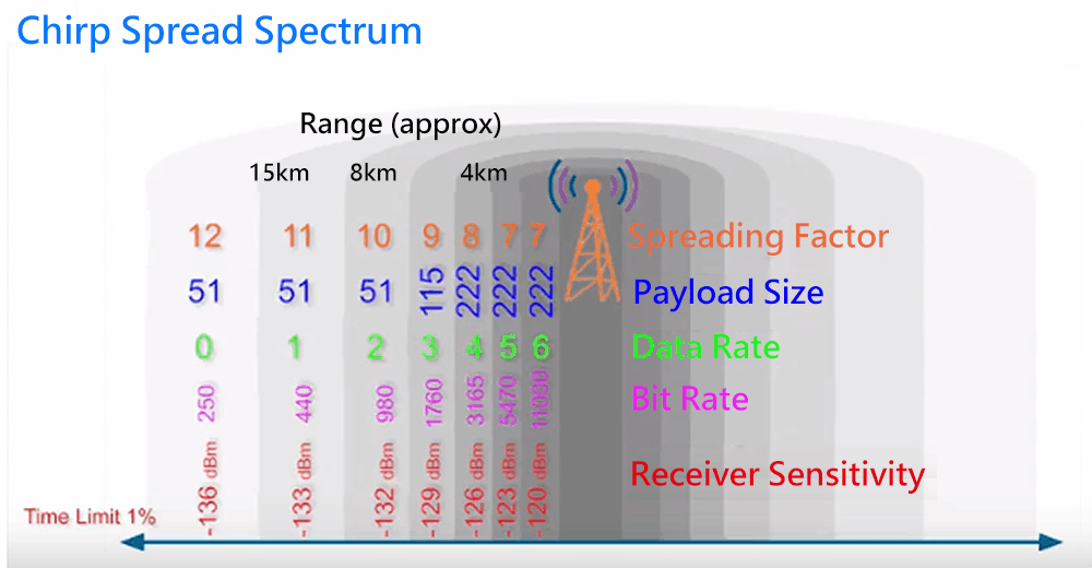
Das obige Spread-Spektrum dient nur als Referenz
Configure Modbus Parameters via web interface
Die LoRa-Übertragungsreichweite kann durch Panel- und Omniantennen mit hoher Verstärkung erweitert werden
| Antennentyp an einem Ende | Antennentyp am anderen Ende | Übertragungsreichweite im freien Freiraum | Anmerkung |
| 2 dBi standard | 2 dBi standard | Up to 800 meters | |
| 3 dBi omni antenna | 3 dBi omni antenna | Up to 1.5 km (1,500 meters) | |
| 3 dBi omni antenna | 6 dBi panel antenna | Up to 2.5 km (2,500 meters) |

Unterstützen Sie LoRaWAN NICHT
Kommunikation mit dem LoRa-Gerät des Drittanbieters nicht möglich
| CPU | 32 bits MCU ,40 MHz , 16KB SRAM, 128KB Flash ROM |
| LoRa | Semtech SX1272 Frequency : ISM band 862 ~ 936MHz Receiver Sensitivity : -137 dBm Transmit Output Power : 20 dBm Sleep Current : 3uA (at power down state) TX current < 140 mA@20 dbm , RX current < 10 mA Security processor ( 128/192/256 bits AES ) Packet engine up to 256 bytes with CRC Antenna : SMA Type , 2 dBi , changeable Distance : Up to 800 meters in free open space Data Rate : 9600 or 19200 bps (between LoRa converter and the equipment connects to it) Application mode : Star |
| Setup-Tool | Windows Utility |
| Stromversorgung | DC 9 ~ 24V / 150ma @ 9V , 60ma @ 24V |
| LED-Anzeigen | SYS (green) , Rx(red) , Tx(green) |
| Betriebstemperatur | -10 °C ~ 70 °C |
| Lagertemperatur | -20 °C ~ 80 °C |
| Abmessungen | 100 x 90 x 25 mm ( W x D x H ) |
| Gewicht | 150 g ( not include power ) |
| Ethernet | Port Type : RJ-45 Connector Speed : 10 / 100 Mbps ( Auto Detect ) Protocol : ARP , IP , ICMP , UDP , TCP , HTTP , DHCP Mode : TCP Server / TCP Client / UDP / Virtual Com / Pairing Setup : HTTP Browser Setup Security : Login Password Protection : Built-in 1.5KV Magnetic Isolation |
| Modbus-Funktion | Modbus TCP to RTU Slave Modbus TCP to ASCII Slave Modbus RTU to TCP Slave Modbus ASCII to TCP Slave |
